The Bench Test Is Not the Real Test
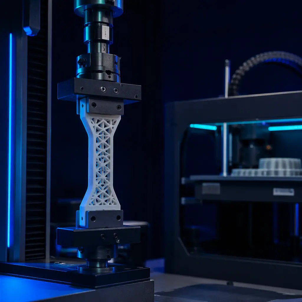
A tensile test reports how much a material can take before it breaks, measured in seconds. Real parts do not get one clean pull; they get a load held for a year, or a load applied and released ten thousand times. Polymers respond to those two cases differently than metals do, because they are viscoelastic — their behaviour depends on time and temperature, not just on stress. A part can survive an instant load by a wide margin and still be the wrong part for a load it must carry for years.
So the useful question is not the peak strength but the sustained or repeated capacity. For the design rules that frame this, our DFAM design rules guide and our dimensional accuracy guide set the baseline for a reliable part.
Creep: Deformation Under Sustained Load
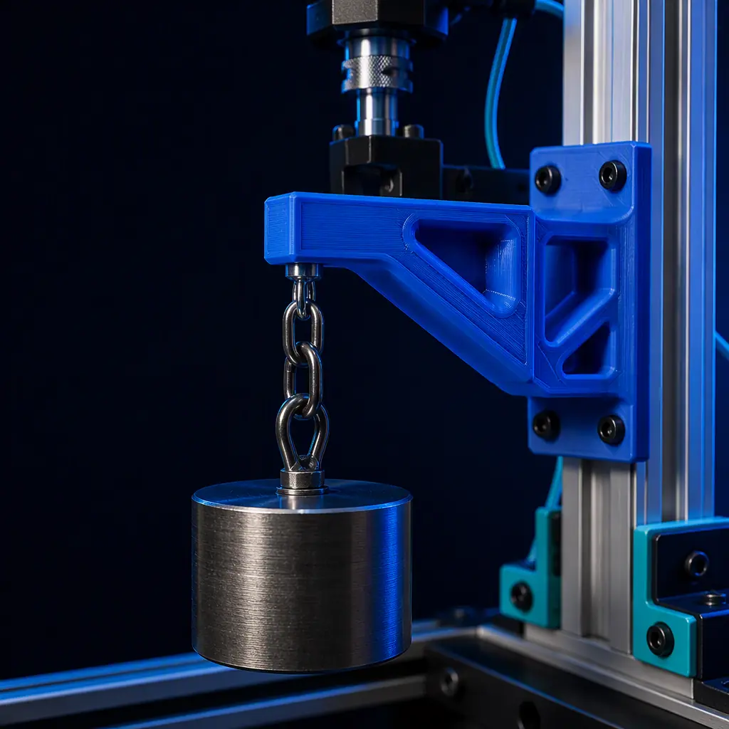
Creep is the slow, time-dependent deformation of a material under a constant load. Hold a tensile weight on a plastic part and it stretches a little, then keeps stretching, faster than you would expect. The engineering quantity is the creep modulus — the effective stiffness over time — which always falls below the instantaneous modulus. For a shelf bracket, a clamp, a cover that must stay tight or a gasket, creep is what gets you if nothing else does.
Creep is roughly linear in the log of time: the deformation grows steadily, and a small load can still accumulate into a large one over a long period. The rule a distributor should carry is to check the sustained load against the creep data for the material, not the yield stress. Our infill & strength guide explains how the internal structure changes that sustained capacity.
Fatigue: Failure Under Repeated Load
Fatigue is the failure of a material under a load that is applied, released and applied again. Metals and plastics both fatigue, but polymers accumulate damage differently, and a printed part adds a layer seam as a ready-made crack path. The standard picture is an S-N (stress vs. number of cycles) curve: at a high stress the part fails after few cycles, and as the stress falls the number of cycles to failure rises until, for many plastics, it levels off at a fatigue or endurance limit.
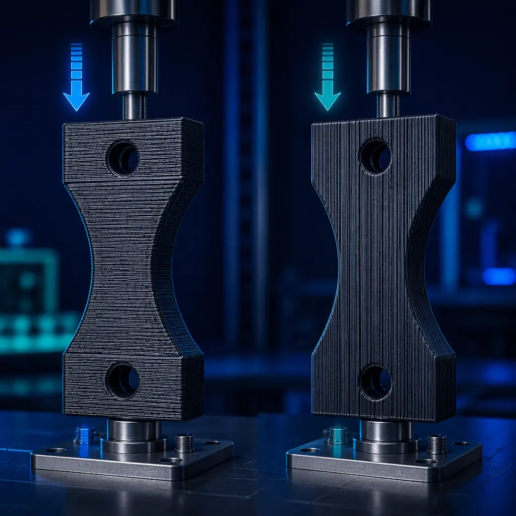
Two things make a printed part worse at fatigue than a moulded one. First, the layer interface is a plane of weakness where a crack can initiate. Second, printed parts are anisotropic — they are much stronger along the layer lines than across them, often by a factor of two or three. For the component applications that live on cyclic load, our gears & bearings guide is the direct reference.

The Material Map a Distributor Should Have
The table below is the quick reference for long-term behaviour. The glass-transition temperature (Tg) is the marker that matters most: above it, a polymer softens and both creep and fatigue accelerate sharply. The anisotropy figure is the practical ratio between across-layer and along-layer strength in a printed part.
The two rows to read together are the Tg and the layer ratio. A material with a low Tg used near its limit is a part that will creep even at a modest load, and an anisotropy of three-to-one means a part loaded across the layers is only a third as strong as the same part loaded along them. For the polymers that carry load well, our polycarbonate guide and our PEEK/PEI/PPSU guide are on point.
Design Rules That Delay Failure
You cannot change a polymer’s chemistry, but you can design so the creep and fatigue never get the chance to matter. The big levers are load direction, stress concentrations and temperature margin:
- Orient the load along the layers — the strongest direction is in-plane.
- Fillet every corner — sharp internal radii are where fatigue cracks start.
- Add ribs instead of thick walls — stiffness without a stress riser.
- Keep a temperature margin — stay well below Tg for a loaded part.
- Apply a duty factor — design the sustained load below a fraction of the static.
For the fastener and joining side that determines how a load is introduced, our heat-set inserts guide and our annealing guide round out the picture of how to make a printed joint survive.
How to Answer “How Long Will It Last?”
When a customer asks for a lifetime, give them a structured answer rather than a number pulled from nothing. Establish the load (sustained or cyclical) and the temperature. Pull the creep modulus and the S-N curve for the material at that temperature. Apply the anisotropy correction for the layer orientation. Then be honest about the margin — state that the figure is a design estimate, and that the only way to confirm it is a load test in the real condition.
What you're looking for: If the suggestion is a high-yield plastic with no thought to creep or to Tg at 60°C, the clip will sag and loosen long before two years — pick a material with a Tg comfortably above 60°C, keep the sustained load well under its creep strength, and orient the print so the layers run along the load.
For the transition from prototype to a real production part that has to carry load, our end-use functional parts guide and our urethane casting guide cover the shorter-run manufacturing route.
How Precise3D Builds Reliable Load-Bearing Parts
At Precise3D we run a 3,500 sqm Shenzhen production network with four assembly cell groups and a dedicated burn-in and aging line, and every unit is power-tested and print-tested before packing. Our CoreXY machines use a rigid enclosed metal chamber and a direct-drive extruder — the mechanical foundation that holds layer accuracy and repeatability over long runs, which is what a part that must not creep actually depends on.
We supply the engineering materials and the design guidance a distributor needs to answer the lifetime question honestly, and our custom branding and OEM white-label starts at 100 units. The fastest honest validation is a one-to-five-unit sample order at wholesale pricing, load-tested in your own application before you commit. For the material and strength balance behind a reliable part, our infill & strength guide is the companion to this one.
Reviewed by the Precise3D OEM & distribution team. Creep, fatigue and Tg values are indicative and depend on the specific grade, print parameters, infill and service conditions; always validate with a load test in the real environment before using a printed part in a load-bearing, safety or critical application.
Engineer It to Last
Need a Part That Holds Under Load?
Join our network of global distributors. Rigid, reliable machines and the engineering guidance that turns a prototype into a part that keeps its shape and its strength.