What Ra and Rz Actually Measure
Roughness is measured by tracing the height profile of the surface and converting it into a single statistic. The two statistics differ in what they emphasize, and choosing the wrong one can make a good part look bad or a bad part look good.
Ra is the arithmetic average of the absolute deviations of the profile from the mean line. It is a global average, so it is robust to the occasional single spike or scratch — a small defect barely moves an Ra value. Rz is a peak-to-valley measure: the average of the five highest peaks and five deepest valleys over a sampling length. It is far more sensitive to a single machining mark, a layer-line step, or a chip-out, which is precisely why it matters on surfaces that will be felt or that must seal.
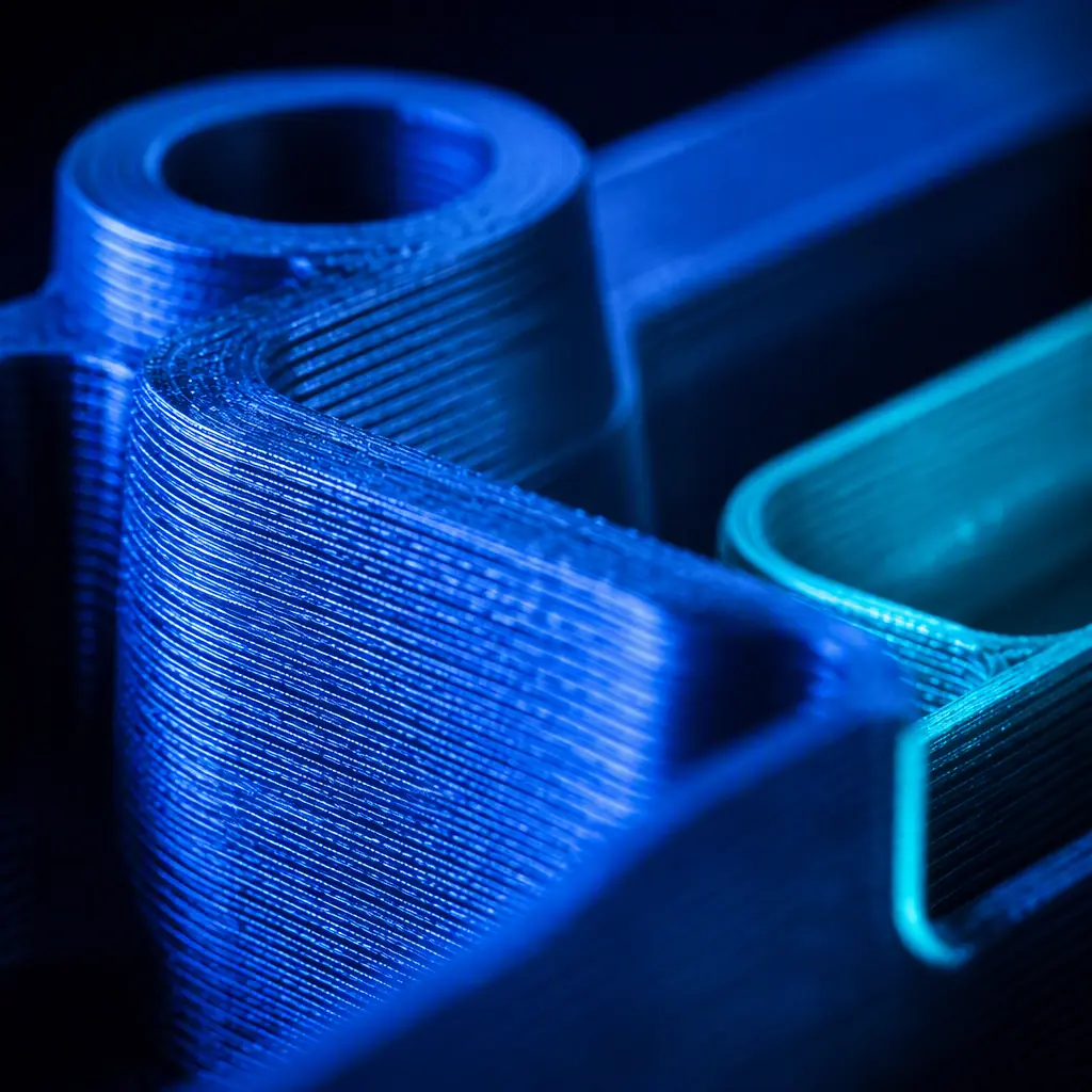
Because a printed part is built up in layers and has directional artifacts, the roughness on a printed part is not isotropic — it is different measured across the layer lines than along them. That is a key difference from a machined part and it is why a printed surface should be measured in the direction the customer cares about, and why a single Ra number without a direction can be misleading. The dimensional side of holding a printed part is covered in our tolerances and accuracy guide.
Typical Ra Values Across Additive Processes
The range you can actually achieve depends heavily on the process. It is worth giving a customer a realistic number up front rather than promising a mirror finish that no machine in that category can deliver without post-processing.
Two caveats apply. First, these are typical built values for the horizontal (top) face; a vertical or overhanging surface prints rougher because of layer stepping and support interaction. Second, the built value is usually what a customer really needs — because that is what the machine produces without any hand-work. Pushing a printed part all the way to a polished <1 µm value rarely adds function; it adds cost. The process and the economics of that finishing work are covered in our post-processing and finishing guide.
How Surface Roughness Is Measured
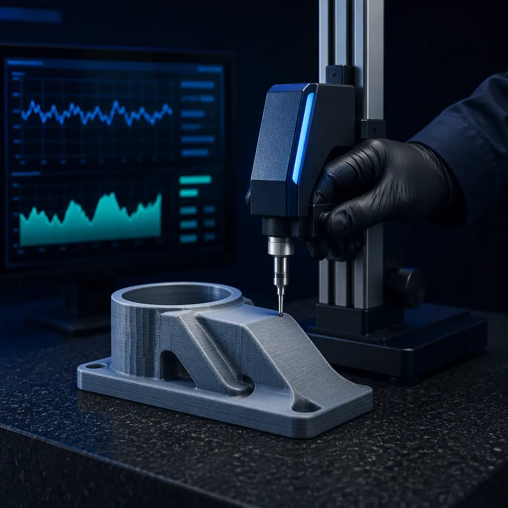
Measurement is where roughness specifications get agreed or disputed, so it helps to know the two main approaches and what each one can and cannot see.
- Stylus (contact) profilometer. A fine diamond-tipped stylus drags across the surface and records the height. It is the classic reference method and the standard most drawings assume. It reads a long trace accurately, but a 2 µm-radius stylus can miss the bottom of a very deep, narrow pit.
- Optical (non-contact) profilometer. White-light or confocal instruments map the surface without touching it. They capture fine detail and can measure a full area rather than a line, which suits a printed surface with complex texture. They can, however, be fooled by a highly reflective surface or one that is very smooth.
Two more things to keep straight. The first is cut-off length — the sampling window over which the roughness is averaged. A short cut-off filters out the long-wavelength waviness; a long one includes it. If the customer does not state a cut-off, a disagreement is waiting to happen. The second is to separate roughness from waviness and from form error. A printed part with a 50 µm warp and a 5 µm surface finish has both a form problem and a roughness value; only the roughness is what Ra reports. Measuring whether the part is flat and on size in the first place is the subject of our incoming QC guide, which is the place to start before you even discuss surface finish.
Design and Orientation Rules That Control Finish
Roughness on a printed part is not random luck — it is largely a consequence of how the part is sliced, oriented and supported. A few rules pull the built surface toward the finish the customer wants.
- Reduce layer height. Halving the layer height from 0.2 mm to 0.1 mm roughly halves the step height and improves both the surface and the detail. It also increases print time, so it is a cost trade-off.
- Orient the visible face up. The top face of a part always prints smoother than a vertical wall. If the customer cares about one face, orient it up.
- Avoid supports on a visible face. Support removals leave scars and rough spots. Design to keep supports away from the surface that gets measured.
- Vary the wall overlap and flow. A slightly over-extruded wall is smoother but risks blobs; under-extrusion gives a rough, under-filled line. Calibrating flow is refined in our calibration and flow guide.
- Use a finer nozzle. A 0.25 mm vs 0.4 mm nozzle gives a finer line and a finer finish, useful on small detail parts.
For the parts that must be smooth in service — sealing faces, bearing bores, optical housings — the practical route is to print close then finish to the spec, rather than to chase a sub-micron Ra entirely in the print.
When to Specify Ra vs Rz
The choice between Ra and Rz is a functional decision, not a style one. Getting it right avoids two failure modes: over-specifying (paying for a finish the part does not need) and under-specifying (shipping a part that fails in use).
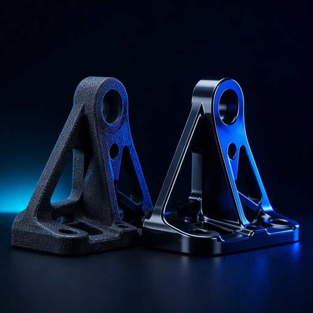
A useful rule of thumb: Ra for how it looks and feels on average; Rz for whether it will leak, catch or not seat. And when you quote an Ra without giving the measurement direction, the cut-off and the process, you are leaving the customer’s QC team free to measure it the way that suits them. Specifying finish tightly starts with the receiving inspection in our incoming QC guide and ends with a documented measurement method.
The Real Cost of a High Finish
A polished <1 µm finish on a printed part is rarely free, and the cost curve is steep at the fine end. Getting from a built 15 µm down to about 5 µm costs relatively little — a finer layer, maybe a light sand. Getting below 1 µm typically needs abrasive flow, vapour smoothing, beads, or a hand-polish, each of which adds labour and sometimes a second process.
That cost should be surfaced before you quote. It is often cheaper to relax the spec to a finish the part genuinely achieves and to change the design — an o-ring seat, a masking, a machined feature on the sealing face — than to pay to polish the whole part. This is the kind of DFM trade-off captured in our design rules guide. Knowing when a printed surface is good enough for a given use is also what makes our end-use parts guide a useful companion: a part that is going into service is the one where finish specification genuinely pays off.
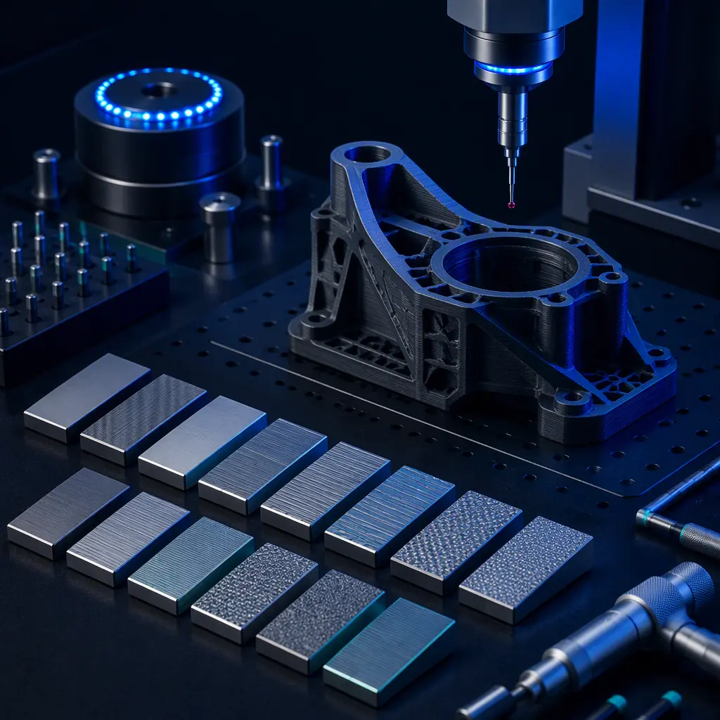
What you're looking for: If the answer is unclear, the part is at risk of a late dispute. Confirm the Ra or Rz value, the cut-off, the measurement direction and the measuring instrument before you quote. Specify the process-typical built value for the material, orient the face you care about upward, and quote the finish you can achieve repeatably — not the theoretical best.
How Precise3D Controls Surface Finish
At Precise3D we run a 3,500 sqm Shenzhen production network with four assembly cell groups, a dedicated burn-in and aging line, and an incoming and outgoing QC bench wired around a documented control plan. Surface finish is treated the same way as a dimension: it is specified, measured and recorded rather than judged by eye.
Our OpenSource1 and Pro X1 platforms deliver a 500×500×500 mm build volume at up to 600 mm/s with a 320°C hotend, and support the fine layer heights and nozzle options that let us hit a usable built finish for a range of engineering materials. Every unit ships with CE LVD (EN 62368-1:2014+A11:2017) and RoHS (EU 2015/863) documentation, and we can supply a measured surface-roughness report on a job where the customer needs the number on the drawing verified. That is the difference between a shop that polishes and a shop that can prove what it shipped.
Reviewed by the Precise3D quality and engineering team. Achievable surface roughness varies by material, print orientation, post-process and measurement method; always agree the specific Ra or Rz value, the instrument and the cut-off with the customer before committing to a guaranteed finish.
Measured, Not Judged
Need a Printed Part with a Guaranteed Surface Finish?
A controlled process, real measurement, and a documented report on the surface you actually shipped. Engineering and production for distributors who sell parts with numbers on the drawing.