Why a Printed Part Needs a Different Inspection Plan
Machined and moulded parts are inspected with assumptions that do not hold for additive parts. A milled part is assumed uniform in the material; a printed part is built layer by layer, so its strength, its expansion and its surface all vary by direction. A moulded part has a deterministic shrink; a printed part's residual stress can bow a tall wall by more than the whole size tolerance.
Three practical consequences follow. First, you must measure in the direction the customer cares about. Second, you must separate form error (is it flat and true?) from size error (is it the right distance?) from position error (is the hole where the drawing says?). Third, you must decide what is genuinely spec-critical — a cosmetic outer surface and a bearing bore are not measured the same way. Getting the inspection plan right starts with the capabilities you actually promise, which is covered in our tolerances and accuracy guide.
The Three Error Types You Are Really Measuring
Put any part on a machine and the reading tells you three different things at once. Confusing them is the most common reason an over-specified job fails inspection and an under-specified one ships defects.
A part can be on size and still fail because it is bowed; it can be perfectly flat and still fail because the holes are 0.3 mm off. When a customer pushes back, the question "measured where, and against which datum?" is what separates a real defect from a measurement disagreement. The calibration routines that keep a machine producing within its envelope are the subject of our calibration and flow guide.
The Instruments: CMM, CT Scanning, Laser & Optical, Hand Tools
Instrument choice is a trade-off between accuracy, speed, what you can reach, and what you can afford. A few rules keep the budget sensible.
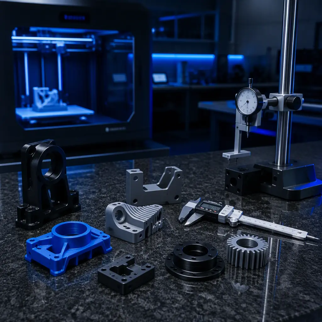
- Calipers and micrometers. Affordable, fast, good to roughly ±0.02 mm on a clean, flat feature — but they cannot measure an internal cavity, a deep bore, or a complex freeform. Use them for the simple checks on every batch.
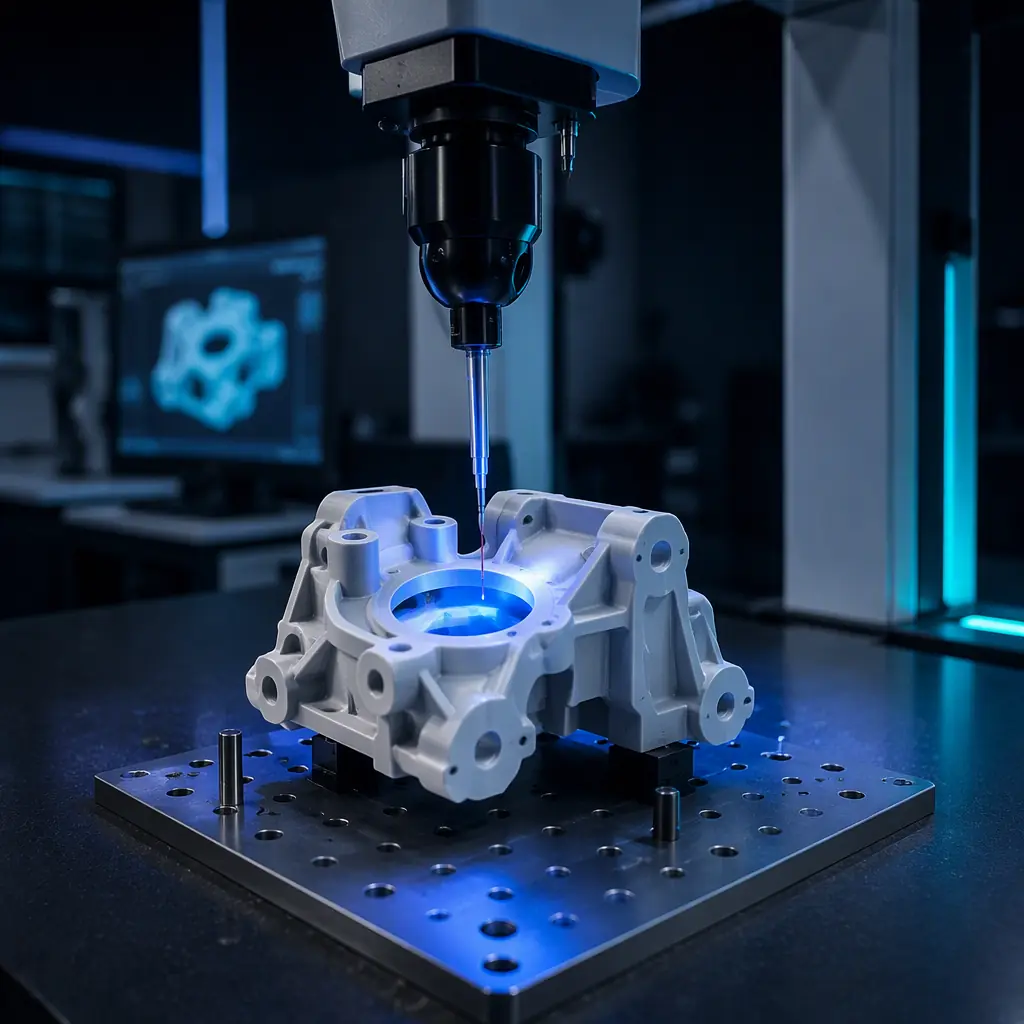
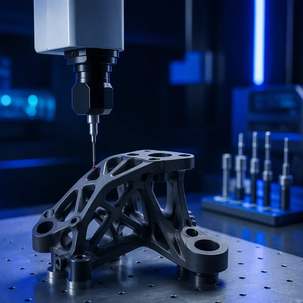
- Coordinate measuring machines (CMM). A touch probe reads a series of points and reconstructs size, form and position with a quoted uncertainty. A benchtop CMM is the workhorse for a printed-part shop and the standard the customer's own QC expects.
- Laser and structured-light scanning. Non-contact, fast, captures the whole surface and produces a point cloud that can be compared to the CAD model. Excellent for freeform and organic parts; accuracy is typically coarser than a CMM, and reflective surfaces need care.
- Computed tomography (CT). The only method that sees inside a part — internal channels, hidden voids, wall thickness. Expensive and slower, but the right answer for a critical internal feature you cannot reach any other way.
The engineering judgment is not "buy the most accurate instrument." It is "buy the instrument whose uncertainty is comfortably smaller than the tolerance you are being asked to hold — and no smaller, because that is money you do not need to spend." Choosing a printer that holds tolerance well in the first place, and what to confirm on incoming machines, is covered in our incoming QC guide.
GD&T: Putting the Tolerance on the Right Feature
Geometric dimensioning and tolerancing is the language that stops "it's within a millimetre" from meaning ten different things. The drawing tells you what is actually functional and what is decorative, and a printed-part job lives or dies on reading that correctly.
The key idea is the datum — the reference feature everything else is measured from. A common failure is inspecting a feature against the wrong datum, which makes a part that is fine look bad. On printed parts, the datum should be a feature the process controls well (a flat bottom face, a printed boss) rather than a thin wall or a snapped-off support surface. Also be aware of bonus tolerance: when a position tolerance uses the maximum-material-condition modifier, the part gets extra tolerance as the feature shrinks away from MMC — which is very forgiving on a printed part that tends to come out on the slightly small side.
First Article Inspection and the Calibration Artifact
Before you inspect a run, you prove the inspection is trustworthy with a calibration artifact — a known-reference part whose features have certified values. Measure it, and if the instrument reproduces the certified value to within its uncertainty, the system is sound. This is the step that makes your numbers defensible rather than asserted.
Then run a first-article inspection on the actual part: the complete set of dimensions, on the first part of a run, against the drawing, documented. This is where you catch a bad orientation, a changed datum, or a support scar on a sealing face before it costs you a whole batch. In a production setting, first-article inspection is also how a customer qualifies you to repeat a job — the same discipline used in an audited manufacturing environment, which we describe in our factory audit and QC checklist.
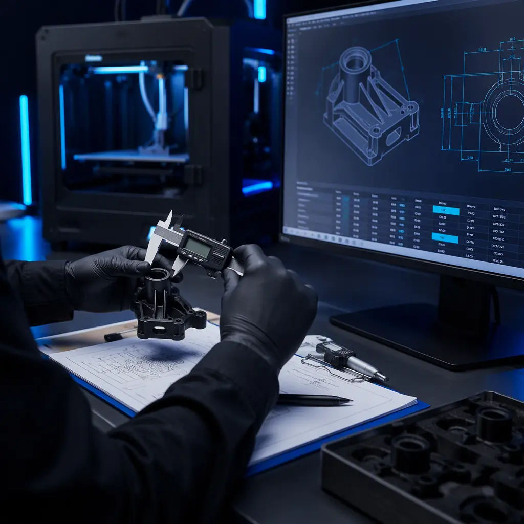
Measurement Uncertainty: Why the Number Is Never the Whole Story
Every measurement is a range, not a point. If your instrument has an uncertainty of ±0.01 mm and you read a feature at 25.00 mm, the part is not "exactly 25.00" — it is 25.00 ±0.01. When tolerance is tight against that range, two shops can measure the same part and reach different verdicts, which is exactly how a dispute starts.
The practical rule is the 1-to-10 rule of thumb: pick an instrument whose uncertainty is about one-tenth of the tolerance you are holding, so the measurement does not eat the budget. Below that you are over-inspecting; above it you are gambling. Agreeing the instrument, the measuring force and the temperature before the job, and writing it into the inspection plan, removes most of the argument. The cost side of working to a tight spec is laid out in our post-processing and finishing guide.
What you're looking for: If the answer is vague, you are arguing about a number you do not control. Ask for the datum, the measured feature and the instrument. Confirm your own instrument's uncertainty is at least ten times smaller than the tolerance, measure on a calibrated artifact first, and verify the part against the drawing's actual datum rather than a convenient edge.
Building an Inspection Plan That Scales
A single well-measured part is luck; a plan that handles hundreds is engineering. The structure is the same whether you make ten parts or ten thousand.
- Identify critical-to-quality features. Not everything on the drawing is functional. Decide the few features that affect fit, function or safety and inspect those on every part.
- Use a documented plan. Feature, instrument, datum, target value, acceptable range. Written down, so two inspectors get the same answer.
- Check the process, not just the part. Monitor drift: if the second hundred parts trend differently from the first, the machine calibrations are the culprit, not the material.
- Escalate on trends, not single readings. One outlier re-measured and confirmed; a trend triggers maintenance.
The same process discipline that drives inspection quality is what makes a part suitable for real use, which is the focus of our end-use parts guide.
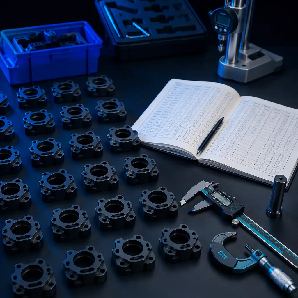
How Precise3D Controls Dimensional Quality
At Precise3D we run a 3,500 sqm Shenzhen production network with four assembly cell groups, a dedicated burn-in and aging line, and an incoming and outgoing QC bench wired around a documented control plan. Dimensional quality is treated as a controlled process, not a hope: machines are calibrated to an artifact, first articles are recorded, and critical-to-quality features are measured on a plan rather than judged by eye.
Our OpenSource1 and Pro X1 platforms deliver a 500×500×500 mm build volume at up to 600 mm/s with a 320°C hotend, and the rigid, well-calibrated motion systems that keep a printed part squarely inside its tolerance band. Every unit ships with CE LVD (EN 62368-1:2014+A11:2017) and RoHS (EU 2015/863) documentation, and where a customer needs the number on the drawing verified, we can supply a documented dimensional inspection report with the instrument and measurement method stated. That is the difference between telling a customer a part is accurate and showing them that it is.
Reviewed by the Precise3D quality and engineering team. Achievable dimensional accuracy varies by material, geometry, print orientation, post-process and inspection method; always agree the feature, datum, instrument and measurement-uncertainty budget with the customer before committing to a guaranteed dimension.
Measured, Not Assumed
Need a Printed Part That Raises to a Spec on the Drawing?
Calibrated equipment, a documented inspection plan, and a report on the dimensions you actually shipped. Engineering and production for distributors who sell parts with numbers on the drawing.