Why Combine Additive with Overmolding
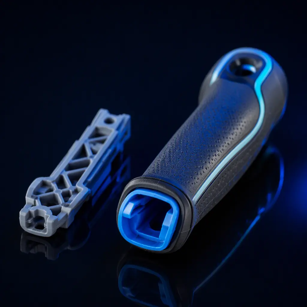
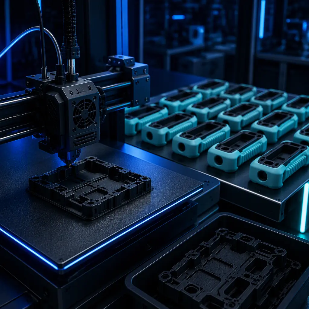
Overmolding is a secondary process: a rigid core is loaded into a mould and a second polymer is shot around it to form a soft grip, a button, a seal, an anti-slip pad, or a chemical- or impact-resistant skin. The technique is decades old. What changes with 3D printing is where the core comes from. A machined or moulded core is expensive to make in small numbers because the geometry is locked into a tool. A printed core costs almost nothing to change, so the core can be iterated a day before the soft tool is ordered.
That combination is a real sweet spot for the distributor who sells into medical devices, power tools, consumer electronics and industrial equipment. It is also the reason hybrid manufacturing — using 3D printing and injection moulding together rather than treating them as rivals — has become a practical production strategy rather than a niche. That relationship is the subject of our injection moulding vs 3D printing hybrid guide, and this article focuses on the overmolding half of it.
The Three Ways to Combine
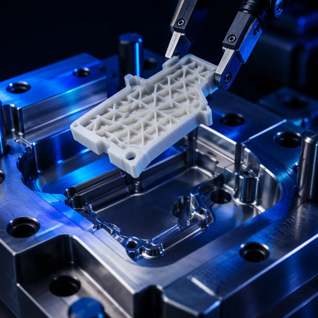
Not every “hybrid” part is assembled the same way. There are three distinct routes, and they differ in cost, strength and how the seam between the two materials is formed. Choosing the right one is the first design decision.
Insert overmolding is the workhorse. The printed core carries the stiffness and the mounting; the overmold carries the soft, tactile surface. Because the core is printed, the whole assembly can be prototyped and validated before any tooling is cut, which is exactly the kind of design freedom described in our DFM and design rules guide.
Material Pairing: What Bonds and What Just Sits There
The chemistry between the rigid core and the soft overmold decides whether you get a bonded part or a part that delaminates on the first pull. Two families of thermoplastic elastomer dominate soft-overmold work: TPE / TPE-S for general grips and TPU for parts that need to absorb knocks, and silicone for parts that need thermal or chemical resistance but a poor bond to most thermoplastics.
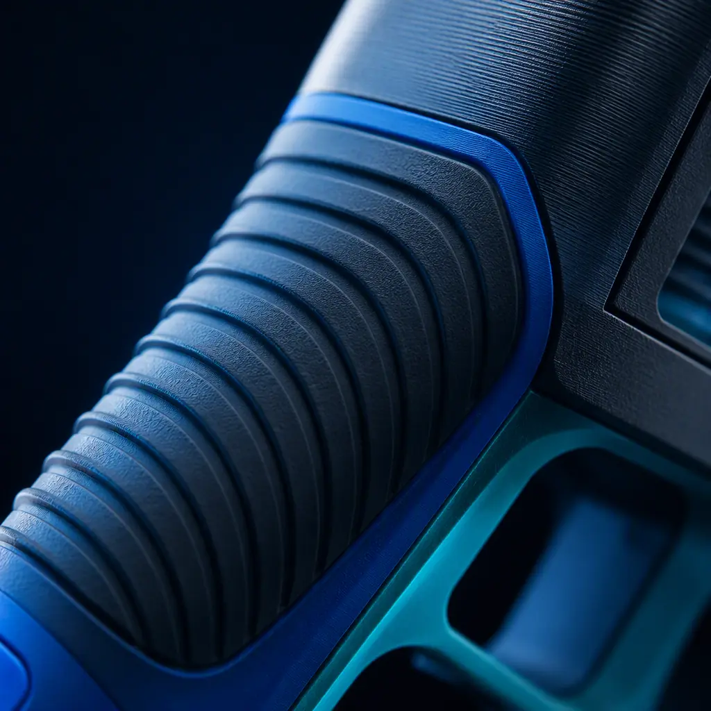
Two rules matter more than the chemistry. The first is shore hardness: a soft overmold that is too hard feels like plastic, one that is too soft tears on a sharp core edge. A shore A range of 60–80 is the common comfort zone for a hand grip; lower values are used for vibration-damping gaskets. The second is surface roughness on the core. A printed core that is too smooth gives the overmold nothing to key into, so a slight texture or a mechanical undercut is often the difference between a bond and a slip. The surface-finish story is covered in our tolerances and accuracy guide, and the post-treatment in our post-processing guide.
Design Rules for the Printed Insert
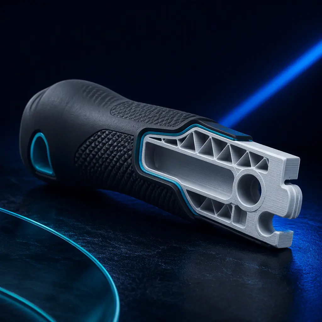
Before you commit a printed core to an overmoulding tool, four design choices decide whether the part survives the moulding pressure. These are the same kind of rules that keep a core from walking or cracking.
- Draft. Give the printed core enough draft (commonly 1–2° on the vertical faces) so it releases from the tool and does not drag damage that would leave a flash.
- Wall section. Keep a minimum wall of 1.2–1.5 mm on the printed core so it does not warp or collapse under the injection pressure of the overmold.
- Mechanical lock. Add a groove, an undercut or a serrated edge where the two materials meet. A purely flat joint only ever depends on chemistry; a profile lock depends on geometry and will not separate.
- Locating. Add bosses, pins or a pocket to locate the core precisely in the tool. If the core shifts 0.2 mm, the soft wall becomes uneven and the part looks wrong.
- Gate and knit lines. Make sure the overmold gate fills the soft section fully so that the knit line is not in a high-stress area on the grip.
The infill and wall structure of the printed core also matters. A part that is meant to take a load at a boss should use a denser infill pattern there, which is the subject of our infill patterns and strength guide. Orientation of the print should put the strongest plane where the load and the overmold pressure act.
The Actual Process: Insert, Tool, Shoot
The workflow for a hybrid part is straightforward once the design is locked, and it is worth going through in order because each step feeds the next.
- 1. Print the core. Run the printed insert on the appropriate material — typically ABS, PC, or a glass-filled variant for stiffness — at a layer height that keeps the surface workable.
- 2. Condition and clean. Dry, and sometimes vapour-smooth or tumble, the core so the surface is consistent and free of contaminant that would kill the bond.
- 3. Load into the tool. Position the core in the overmoulding or insert-moulding tool on its locating features.
- 4. Shoot the soft layer. Inject the TPE, TPU or silicone around the core at the material’s melt temperature and hold long enough to knit.
- 5. Eject and trim. Remove the hybrid part, trim any flash, and inspect the seam.
The tooling for the overmold is a soft aluminium or resin tool in most low-to-medium volume work, and the printed core keeps the costly hard tooling out of the picture for the geometry that changes most. Where a full production tool is later justified, the printed core is simply swapped for an insert that is moulded, and the same overmold tool is reused.
Tolerances, Shrinkage and the Seam
Two sources of dimensional drift matter in a hybrid part. The first is the printed core’s own shrinkage and layer-based accuracy, which our tolerances guide explains; the second is the overmold’s shrinkage on the core. Soft polymers shrink more than the hard plastics they are shot against, so a long grip that wraps a printed rod can develop a differential that shows as a small bulge or a step at the seam.
The way to control it is to design the seam so that a small mismatch is acceptable and to measure it the same way on every part. For a distributor, the practical implication is simple: do not quote a hybrid part on a total tolerance that depends on both processes staying absolutely in sync. Give the customer a tolerance that reflects the reality, and offer to hold the tight dimensions on the printed core rather than on the flexible seam.
When a Hybrid Part Beats All-AM or All-IM
The decision to go hybrid is an economic one, and it can be stated cleanly. An all-moulded two-shot part only makes sense at a volume that amortises the tooling. An all-printed soft part rarely feels like a real overmould and cannot match the grip performance of a true TPE layer. The hybrid sits in the middle and wins under specific conditions.
This is also where the tooling broader picture matters. A printed core plus a soft overmold tool is a fraction of the cost of a production two-shot tool, and it lets a distributor quote a small program honestly without asking a customer to bet on tooling they cannot justify. The economics and scheduling of that kind of low-volume program are covered in our manufacturing tooling guide.
What you're looking for: If the answer is a flat, smooth joint with no undercut or groove, the part will delaminate. Add a mechanical lock. Draft the core so it releases cleanly, keep the wall heavy enough to resist injection pressure, and locate it solidly in the tool. Measure the seam on every part, because the flexible boundary is the first place a tolerance mismatch shows up.
How Precise3D Approaches a Hybrid Program
At Precise3D we run a 3,500 sqm Shenzhen production network with four assembly cell groups and a dedicated burn-in and aging line, so a hybrid part is a single-owner job rather than a hand-off between two shops. The printed core is made on our own platform, and the overmoulding partner works from a documented design-rule sheet so the interface between the processes is controlled instead of assumed.
Our OpenSource1 and Pro X1 printers run a 500×500×500 mm build volume at up to 600 mm/s with a 320°C hotend, and every unit ships with CE LVD (EN 62368-1:2014+A11:2017) and RoHS (EU 2015/863) documentation, so a two-material part that combines a printed core and a moulded skin ships with a compliance file that covers both. Tooling and low-volume work starts at a project of 100 units per model, which is the volume where a hybrid core-plus-overmold program starts to make real sense.
Reviewed by the Precise3D engineering team. Bond strength, shore hardness and tolerance limits are material-, tool- and geometry-specific; always validate a hybrid part’s adhesion and performance on sample parts before committing to a full production run.
Two Materials, One Part
Ready to Build a Hybrid Core + Overmold Part?
A printed core, a soft-touch skin, and a supplier that owns the hand-off between the two. Engineering and low-volume production for distributors who ship parts that have to feel right as well as measure right.