Why Post-Processing Becomes the Constraint at Scale
Print time is a machine cost, and machines scale by buying more of them. Support removal is a labour cost, and labour does not scale the same way. A farm running twenty printers can absorb finishing inside the operator's shift. The same farm at a hundred printers discovers that support removal has quietly become the bottleneck, and that the queue of unfinished parts is growing faster than the queue of print jobs.
The arithmetic is unforgiving. Hand removal of a moderately supported part takes two to eight minutes depending on tree density and material. At a hundred machines producing four parts per machine per day, that is 400 parts and somewhere between 13 and 53 labour hours of finishing per day, which is two to six full-time operators before anyone touches packing or shipping. Very few farms model this before it happens.
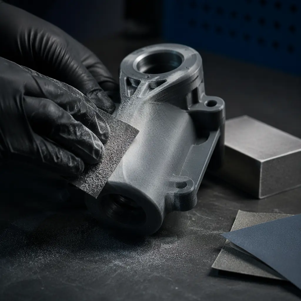
Labour Minutes by Support Type
Before choosing equipment, measure the actual removal time for your own geometry. The table below gives typical ranges for common support configurations, which is enough to size the problem and compare methods.
The last two rows are where most of the confusion sits. Soluble support does not eliminate labour, it converts labour into unattended time plus tank maintenance. Whether that is a win depends entirely on whether your constraint is operator hours or calendar time, and those are different problems with different solutions.
Choosing the Removal Method by Material and Geometry
The selection rule that saves the most money is to separate support removal from surface finishing. They are different operations with different equipment, and a farm that tries to do both in one blast cabinet usually damages tolerances while still not achieving the surface it wanted. Remove mechanically first, then finish only where the customer's specification requires it.
Soluble Supports: One Nozzle vs Two
Soluble support economics get decided at purchase rather than at production. A single-nozzle machine can print soluble interfaces by using the same hotend for both materials, at the cost of purge cycles and a tank that has to dissolve a full support structure rather than a thin interface layer. A dual-nozzle machine prints the interface in soluble and the bulk in the model material, which dissolves faster and uses far less of the expensive filament.
The calculation that matters is consumable cost per part plus tank throughput. Interface-only soluble support typically uses a fraction of the material and dissolves in a few hours; full soluble structures can take many hours and load the tank with dissolved polymer that has to be changed out. Where a farm is already running multi-material for other reasons, the purge and waste economics are covered separately in our purge waste economics guide, and the multi-material hardware assessment in our multi-material systems guide.
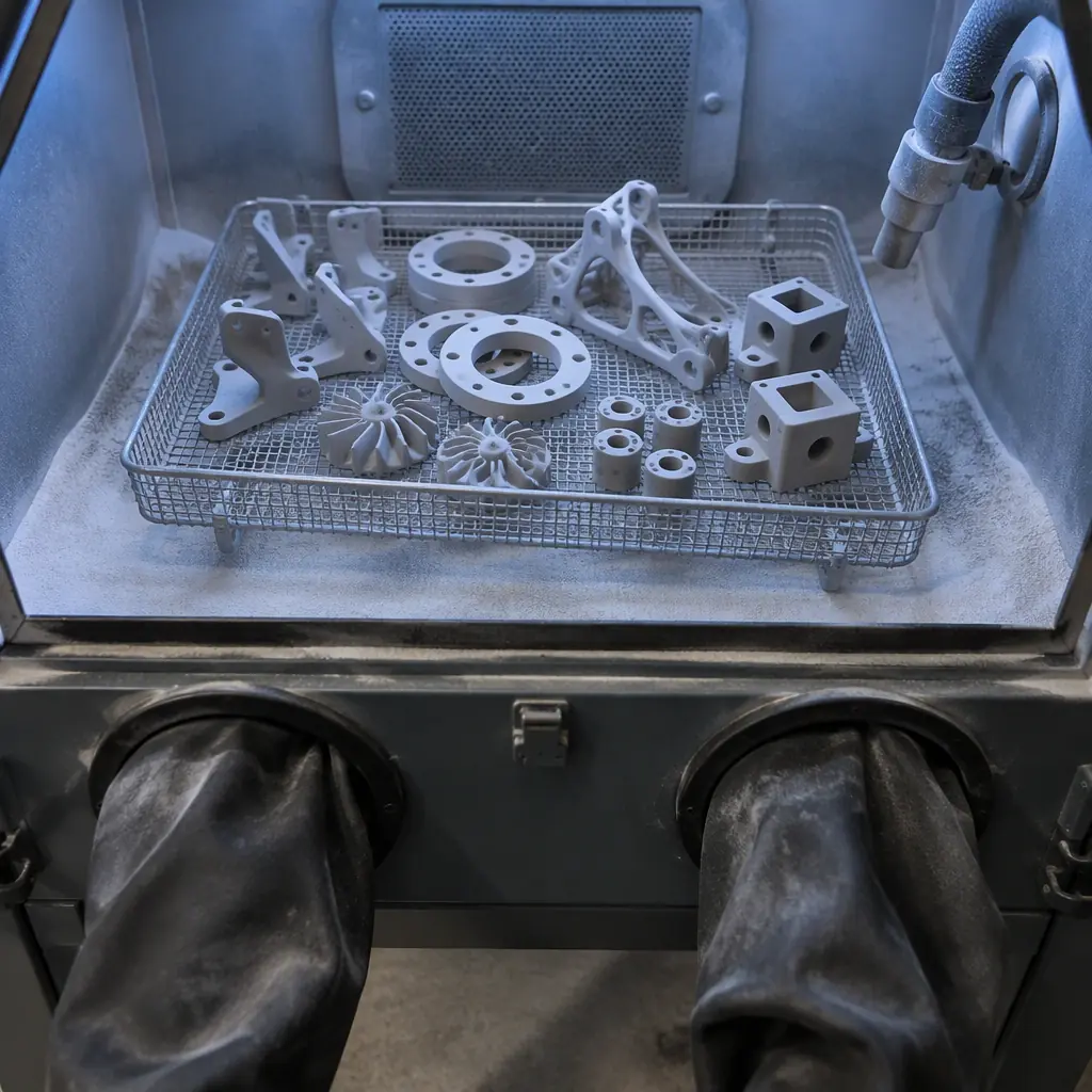
Media Selection for Blast and Vibratory Finishing
Media choice determines both the surface finish and the tolerance loss, and it is the parameter most often set once and never revisited. The table below maps media to outcome for common 3D printed materials.
Bead blasting removes material, and on a functional part that means the dimensions you inspected before finishing are no longer the dimensions you ship. A tolerance-critical part should be measured after finishing, not before, and the blast parameters recorded so the loss is repeatable. The wider question of how post-processing affects dimensional accuracy is covered in our dimensional accuracy and tolerance compensation guide.
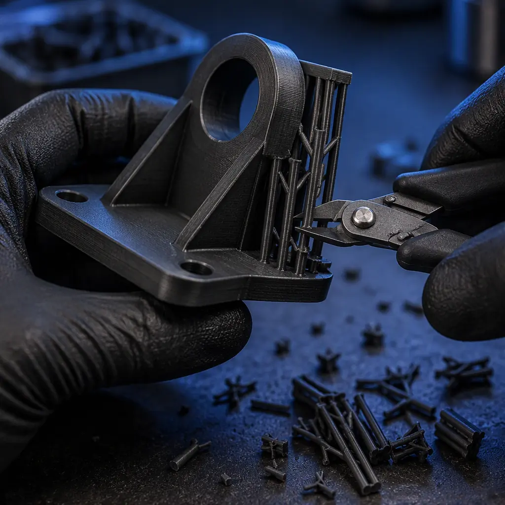
Heat Effects on Dimensions
Several finishing routes introduce local heat, and the materials used in production parts have glass transition temperatures low enough for that heat to matter. Vapour smoothing softens the outer surface and can round edges and shift thin features by a few tenths of a millimetre. Heated tool removal can leave witness marks where the support met the part. Media blasting generates surface heat that accumulates in thin sections when the nozzle dwells.
The practical control is to know the glass transition temperature of each material in production and keep finishing below it, and to re-measure a first article after any change in finishing parameters. PLA at roughly 60 °C and PETG around 80 °C leave little margin against a hot air gun used carelessly. For parts where the finishing operation cannot be controlled tightly enough, change the print orientation instead, which is often cheaper than controlling heat. Orientation strategy is covered in our print orientation guide.
Throughput Planning: Parts per Hour per Operator
Once removal time is known, throughput planning is arithmetic. A single operator with hand tools clears roughly 12 to 20 parts per hour on tree-supported functional parts. A bead blast cabinet with a rotating basket moves 40 to 80 small parts per hour once loading and unloading is counted. A vibratory bowl runs unattended for 30 to 90 minutes per batch and needs perhaps ten minutes of operator time to load and unload, which changes the labour model entirely, from one operator per station to one operator across several bowls.
That difference is what makes equipment pay. Moving from hand removal at 15 parts per hour to a blast cabinet at 60 reduces labour per part by roughly 75 percent, and the cabinet usually pays back inside a year at a hundred-machine production level. The calculation sits alongside the other operating costs of a print cell, which are set out in our print farm economics guide.
Quality Control After Finishing
Finishing is a process step, which means it needs its own controls rather than a visual check at the end. Four controls cover most of the risk: a first-article inspection after any change of media, cycle time or operator; a sampling plan by batch with a stated acceptance criteria for the surfaces the customer specified; a measured surface roughness where the specification calls for one, recorded rather than judged; and retention of first articles so a drift in finish can be traced to a date and a parameter set.
For soft-touch and sealed parts, finishing interacts with the material system, and the sealing behaviour of the elastomer matters more than the finish itself, as covered in our silicone and LSR sealing guide.
Precise3D on Finishing-Ready Architectures
Post-processing cost is influenced upstream, at machine and material selection. Our platforms support high-flow hotends that reduce support density through better overhang performance, dual-material configurations for interface-only soluble support that shortens dissolution from hours to a fraction of that, and documented glass transition data per material so finishing parameters can be set against a real number rather than a guess. Machines ship with CE LVD (EN 62368-1:2014+A11:2017) and RoHS (EU 2015/863) documentation from a 3,500 sqm Shenzhen production network applying a documented control plan at incoming and outgoing QC.
For distributors the commercial point is that finishing capability is part of what the customer is buying, whether or not it appeared in the quotation. A machine that produces parts the customer cannot economically finish is a machine that gets replaced. Configurations and supporting documentation are available on request with MOQ from 100 units.
Reviewed by the Precise3D engineering team. Removal times, surface roughness figures and cycle times above are industry-typical ranges for orientation and are not a specification for any particular machine, material or media combination. Measure your own process before committing to equipment.
Planning a Finishing Cell?
Discuss Multi-Material and Soluble Support Configurations
Tell us your part mix, materials and target throughput. We will recommend the extruder configuration, the soluble interface strategy and the glass transition data per material that lets you set finishing parameters against a real number rather than a trial run.